


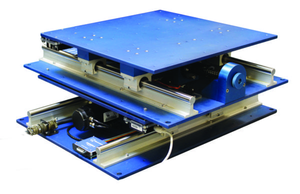
Shake Table III XY
The QuanserShake Table III XY consists of a stage mounted on the ground support plate. The stage is actuated by three linear motors and move in either the x or y directions. Two motors mounted on the ground support plate of the table operate in parallel and power the x-axis. A single motor mounted to the stage actuates the y-axis. Together the motors allow for XY planar motion in the Cartesian arrangement. The displacement and acceleration of the stage are measured by the on-board encoder and the accelerometer sensors. The encoder and accelerometer are connected to the DAQ and their signals can be displayed and processed further. The Shake Table III XY can be programmed through a provided Shake Table software, as well as through QUARC® for MATLAB®/Simulink®.
Shake Table II XY
The Shake Table II XY consists of two single-axis Shake Table II units mounted perpendicularly on top of each other. Each stage can travel ±7.6 cm. Driven by powerful motors, the Shake Table II XY can achieve an acceleration of 2.5 g when loaded with a 7.5 kg mass.
Furthermore, you can use the two Shake Table II from the XY configuration for other setups, i.e., serial and parallel, to support larger loads, or perform experiments with asynchronous excitation signals.

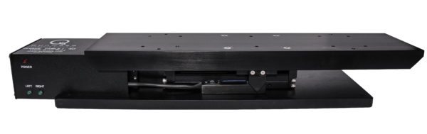
Shake Table II
The Shake Table II consists of a top stage driven by a powerful motor that allows it to achieve an acceleration of 2.5 g when loaded with a 7.5 kg mass. The stage has a travel of 15.2 cm and rides on two ground-hardened metal shafts using linear bearings, which allows for smooth linear motion with low path deflection. The Shake Table’s motor is a 400W high-powered 3-phase brushless DC actuator. The motor contains an embedded high-resolution encoder that allows the position of the stage to be measured with an effective linear resolution of 1.55 μm. An analog accelerometer mounted on the Shake Table II platform measures the acceleration of the stage directly.
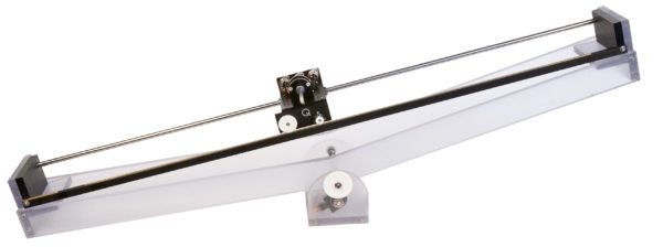
Shake Table I-40
The Shake Table I-40 consists of a stage mounted on a high-quality, low backlash linear guide with a total travel of 40.0 mm and is driven using a ball-screw drive mechanism. Using the high torque direct drive motor, the stage loaded with a 1.5 kg mass can be accelerated up to 1.0 g. The high-resolution encoder enables the system to obtain a linear stage position resolution of 1.22 μm.

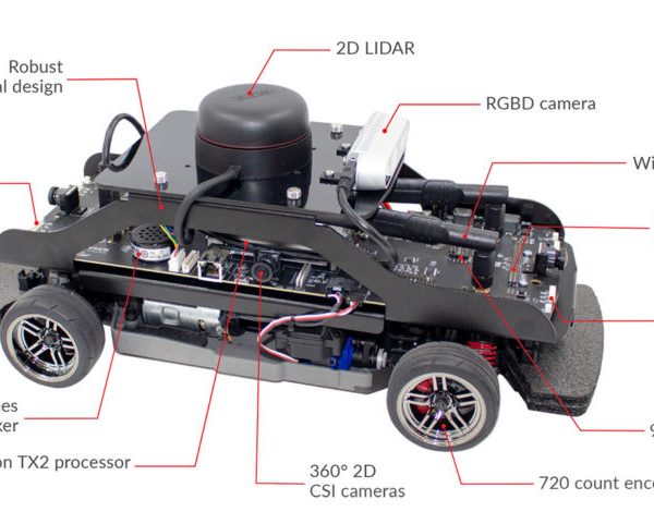
Self-Driving Car Research Studio
The Quanser Self-Driving Car Research Studio is a highly expandable and powerful platform designed specifically for academic research. Use it to jump-start your research and scale your vehicle fleet, while leveraging multiple software environments. The studio brings you the tools and components you need to test and validate dataset generation, mapping, navigation, machine learning, artificial intelligence, and other advanced self-driving concepts.
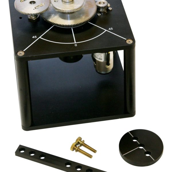
Rotary Servo Base Unit
The Rotary Servo Base Unit is a geared servo-mechanism system. The plant consists of a DC motor in a solid aluminum frame. This DC motor drives the smaller pinion gear through an internal gear box. The pinion gear is fixed to a larger middle gear that rotates on the load shaft. The position of the load shaft can be measured using a high resolution optical encoder or a potentiometer. The encoder is also used to estimate the speed of the motor.
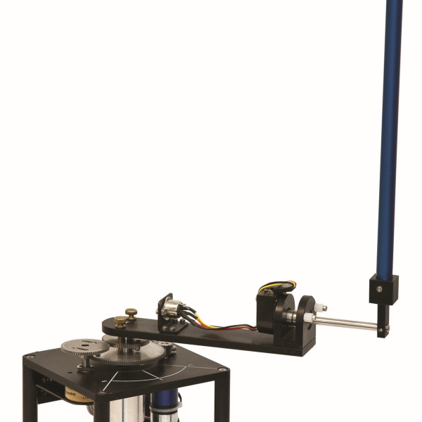
Rotary Inverted Pendulum
Students can use this module to learn practical problem-solving skills for mechanical and aerospace engineering. A classic application context for the design challenge is the two-wheeled Segway self-balancing electric vehicle.
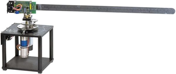
Rotary Flexible Link
The Rotary Flexible Link consists of a strain gage which is held at the clamped end of a thin stainless steel flexible link. The DC motor on the Rotary Servo Base Unit is used to rotate the flexible link from one end in the horizontal plane. The motor end of the link is instrumented with a strain gage that can detect the deflection of the tip. The strain gage outputs an analog signal proportional to the deflection of the link. In this experiment, students learn to find the stiffness experimentally, and use Lagrange to develop the system model. This is then used to develop a feedback control using a linear-quadratic regulator, where the tip of a beam tracks a desired command while minimizing link deflection.

