

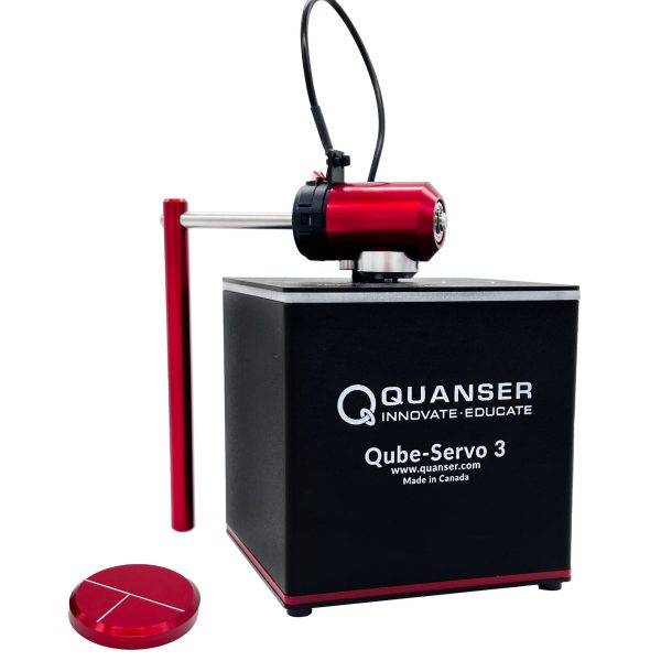

QUBE – Servo 3
THE QUICKEST PATH TO PRACTICAL CONTROLS
The Qube Servo 3 is the fastest and most efficient way to bring modern, hands-on learning experiences into your Control Systems course. The system is equipped with a high-quality direct-drive brushed DC motor, two encoders, an internal data acquisition system, and an amplifier. Connect with USB to a Windows PC using MATLAB Simulink or Python.
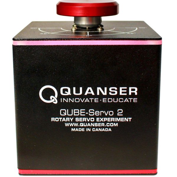
QUBE – Servo 2 USB
Integrating Quanser-developed QFLEX 2 computing interface technology, QUBE-Servo 2 provides more flexibility in lab configurations, using a PC, or microcontrollers, such as NI myRIO, Arduino and Raspberry Pi. With the comprehensive course materials included, you can build a state-of-the-art undergraduate teaching lab for your mechatronics or control courses, and engage students in various design and capstone projects.
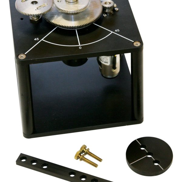
Rotary Servo Base Unit
The Rotary Servo Base Unit is a geared servo-mechanism system. The plant consists of a DC motor in a solid aluminum frame. This DC motor drives the smaller pinion gear through an internal gear box. The pinion gear is fixed to a larger middle gear that rotates on the load shaft. The position of the load shaft can be measured using a high resolution optical encoder or a potentiometer. The encoder is also used to estimate the speed of the motor.
Rotary Inverted Pendulum
Students can use this module to learn practical problem-solving skills for mechanical and aerospace engineering. A classic application context for the design challenge is the two-wheeled Segway self-balancing electric vehicle.
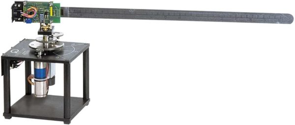
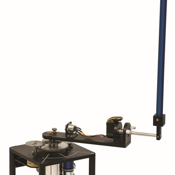
Rotary Flexible Link
The Rotary Flexible Link consists of a strain gage which is held at the clamped end of a thin stainless steel flexible link. The DC motor on the Rotary Servo Base Unit is used to rotate the flexible link from one end in the horizontal plane. The motor end of the link is instrumented with a strain gage that can detect the deflection of the tip. The strain gage outputs an analog signal proportional to the deflection of the link. In this experiment, students learn to find the stiffness experimentally, and use Lagrange to develop the system model. This is then used to develop a feedback control using a linear-quadratic regulator, where the tip of a beam tracks a desired command while minimizing link deflection.
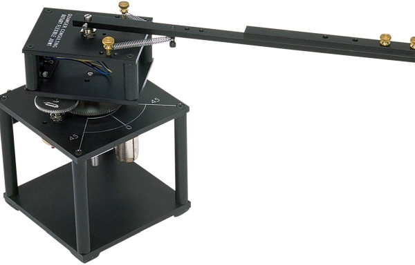
Rotary Flexible Joint
The Rotary Flexible Joint module consists of a free arm attached to two identical springs. The springs are mounted to an aluminum chassis which is fastened to the Rotary Servo Base Unit load gear. The module attaches to a DC motor on the Servo Base Unit that rotates a beam mounted on a flexible joint. The Rotary Flexible Joint module is supplied with three distinct pairs of springs, each with varying stiffness. It comes with three base and three arm anchors for the springs, and allows to obtain a wide variety of joint stiffness. The module is also supplied with a variable arm load that can be mounted at three distinct anchor positions to change the length of the load.
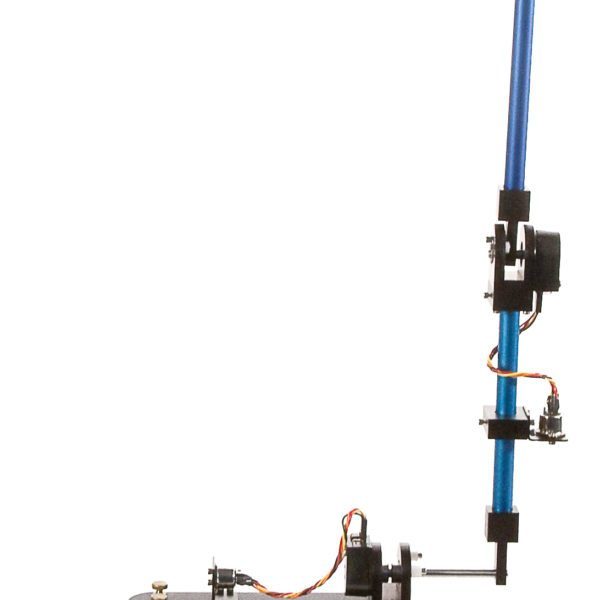
Rotary Double Inverted Pendulum
The Double Inverted Pendulum module is composed of a rotary arm that attaches to the Rotary Servo Base Unit, a short 7-inch bottom blue rod, an encoder hinge, and the top 12-inch blue rod. The balance control computes a voltage based on the angle measurements from the encoders. This control voltage signal is amplified and applied to the Servo motor. The rotary arm moves accordingly to balance the two links and the process repeats itself.

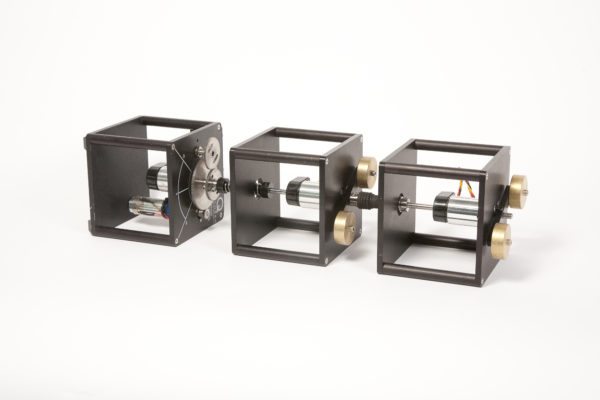
Multi-DOF Torsion
The Torsion Module is a rotary torsional system that consists of an instrumented bearing block, which is mounted in a cubic aluminum frame. A shaft is free to spin inside the bearing block and its angle is measured using an encoder. The shaft can be fitted with either a torsional load or a flexible coupling.
The assembly made of one Rotary Torsion module coupled to a Rotary Servo Base Unit constitutes one Degree of Freedom (1 DOF) torsional system. The Rotary Servo Base Unit lies on its side so that its DC motor and output shaft are horizontal and able to rotate a flexible coupling attached to a rotational load. The torsional load consists of two inertial disc masses, which can be located at different anchor points along their support bar. Up to seven torsion modules can be coupled in cascade to allow for multi-dimensional control problems.

