

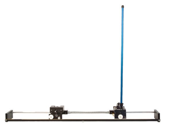
Linear Flexible Joint with Inverted Pendulum
The Linear Flexible Joint with Inverted Pendulum combines two fundamental control challenges to give students an opportunity to a more advanced modeling and control challenge.
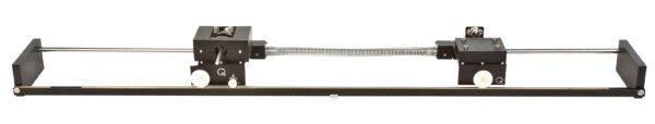
Linear Flexible Joint
The Linear Flexible Joint experiment will help your students learn how to model and control real-world dynamic systems such as flexible couplings and gearboxes.
Linear Flexible Inverted Pendulum
The linear flexible inverted pendulum challenges students to gain advanced modeling and control experience by controlling both the damping of a flexible link, and an unstable inverted pendulum.

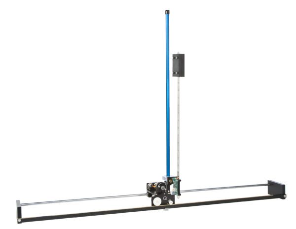
Linear Double Inverted Pendulum
The double inverted pendulum represents a complex challenge with real-world applications that include stabilizing the takeoff of a multi-stage rocket and modeling the human posture system.
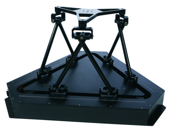
Hexapod
The Hexapod is comprised of six linear ball-screw actuators driven by six DC motors. The ball-screw is based on a high-quality, low backlash linear guide with a total travel of 30 cm and is driven by a high torque direct drive motor. A revolute joint fastens the arms to each motor. For maximum safety, a motor brake control employs the Hexapod’s brakes when the joints reach their limit. Motor position feedback for all six motors is provided by optical encoders that measure the angular position of the motor shaft. An optional six axes ATI force/torque sensor can be installed on the end-effector to capture measurements of forces and torques along all degrees of freedom.

HD² High Definition Haptic Device
As a dexterous haptic device, HD² enables researchers to interact with virtual or remote environments using programmable force feedback. Compared to other commercially available haptic devices, HD² has a large workspace and very low intervening dynamics. This parallel mechanism is highly back-drivable with negligible friction. The heavy-duty capstan drive and high-performance motors reduce the perceived inertia while maintaining rigidity of the device structure.
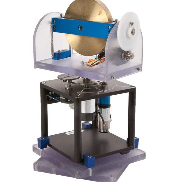
Gyro/Stable Platform
The module consists of a rotating disk mounted inside a frame. The disk is actuated about its center through a DC motor. An internal frame holds the rotating disk and is attached to an external frame through two shafts at both ends. A gear mechanism is connected between one of these end shafts and an encoder measures the angle of the blue frame as it rotates about the shafts, i.e., it measures the disc tilt angle. The Rotary Servo Base Unit is mounted on a 2-plate structure and is free to rotate. This allows the gyroscope structure to be manually rotated relative to a fixed surface in order to simulate external disturbance to the gyroscope system.
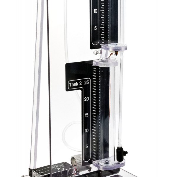
Coupled Tanks
Designed in association with Prof. Karl Åström and Prof. Karl Henrik Johansson, the Coupled Tanks system consists of a single pump with two tanks. Each tank is instrumented with a pressure sensor to measure the water level. The pump drives the water from the bottom basin up to the top of the system. Depending on how the outflow valves are configured, the water then flows to the top tank, bottom tank, or both. The rate of flow can also be changed using outflow orifices with different diameters. The ability to direct water flow, together with variable outflow orifices allows for several interesting Single Input Single Output (SISO) configurations. Further, two or more Coupled Tanks can be combined together for Multiple Input Multiple Output (MIMO) experiments.
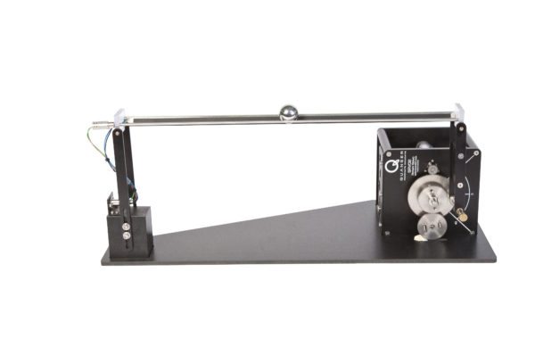
Ball and Beam
The Ball and Beam module consists of a steel rod in parallel with a nickel-chromium, wire-wound resistor forming the track on which the metal ball is free to roll. The track is effectively a potentiometer, outputting a voltage that’s proportional to the position of the ball.
When coupled to the Rotary Servo Base Unit, the tilt angle of the beam can be controlled by changing the servo gear angle. The Ball and Beam module can be operated in stand-alone mode, and the ball position can be controlled via the user interface.

